
- #Qucs library download how to
- #Qucs library download software
- #Qucs library download series
- #Qucs library download simulator
The value of current source is calculate on variable IL(current generate) on equ3 based on equation 9, the value of current saturation on diode is calculate on variable I0on equ3 based on equation 10, the value of resistor series and parallel its calculate manually and indicate on eqn3. The equivalent circuit is formed by following components: current source ( dc current sourceon sourcelibrary), diode ( diodeon non linear componentslibrary) and resistors ( resistoron lumped componentslibrary). Therefore, in Section 4 are calculated parameters using data from the photovoltaic cell indicated in datasheets, for equivalent circuit on figure 1c.įinal result of the simulation Qucs photovoltaic cell The problem is the parameter values of circuit components. Then, this circuit has a simple and accurate model to simulate a photovoltaic cell.
.png "qucs library download")
The circuit of figure 1c is the more commonly used, although in several simulations simplifies the parallel resistance value with a high value, using the series resistance to include effect of fill factor, gets a similar circuit of figure 1d and used Rpto avoid problem with simulation. Other models include two diodes as in figure 1d, and. There are several circuits that include resistors for real effects of a photovoltaic cell, for example, figure 1b includes a resistor in series,, figure 1c includes parallel and series resistance, and. The equivalent circuit of an ideal cell is formed by a current source in parallel with a diode ( figure 1a). Then, can be use PV module study PV grid connection and energy production prediction.Ģ. The model PV module can use to study mismatch effects due to different electrical characteristics of PV cells and the use of pass diode to reduce loss due to partial shadows. The model of PV cell can be used to simulate a PV module, because PV module is an association of cells in series and parallel. Also, can be used to test circuit with photovoltaic solar cell as power supply, in applications such as: micropower systems for harvesting energy, stand alone PV system for control battery charge. Further, can be used an attractive presentation to the student with a real representation of PV cell. This model can be used for training in photovoltaic solar energy, using: subcircuits, curves, tables and equations.
#Qucs library download software
QUCS is a multiplatform application that runs on Windows and Linux, this software is available in Linux distributions for electronics. Additionally, you can use equations to define the model of photovoltaic cell and represent the characteristic curves on the same page. QUCSuses a generic diode for adjust the current and voltage curve (IV curve) at photovoltaic cell.
#Qucs library download simulator
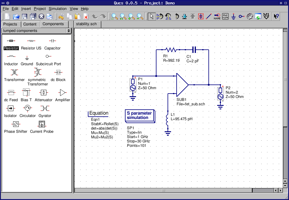
Free software used is Quite Universal Circuit Simulator ( QUCS). The model presented is based on an equivalent circuit implemented in free software. The easiest way to create this is with an s-parameter template as show below.There are numerous studies that develop the mathematical modeling of photovoltaic cells and verified by software, for example or. This is just a human readable csv file that lists the phase/magnitude(or equivalent representation) of the S11 measurement at every frequency. Once measured you will need to export a ‘touchstone’ s1p file. Try to think if you error is likely to be a significant fraction of a wavelength. As normal the accuracy you need for this is dependent upon the required frequency. If we design a matching network it will be assumed that this is where we place our components. We must be very careful to understand the calibration plane of tour antenna. However I will highlight one critical point.
#Qucs library download how to
I won’t go into detail here about how to measure an antenna as this was covered in my previous posts. The Device Under Test could really be any device, but as I am an antenna geek, lets assume its an antenna. Once you get to grips with the basics here, you can always experiment in QUCSstudio with alternate components. However it is possible to use alternative components such as transformers, transmission lines, or even resistors as part of an matching network. Of course, I had totally forgotten!!! But lets go through it again.Ī matching network is normally a network of inductor or capacitors selected to convert from one impedance to another. I was asked in the comments about exactly to do this. This could be used to quickly design antenna matching networks for instance. In my last blog post I alluded to the fact that you could take s1p touchstone files generated by nanoVNAsaver and use this to automatically calculate/simulate a matching network in QUCSstudio.
